Interested in finding more about commercial scale operations to mine gold nuggets? This is my page of information on Commercial placer mining equipment......
| Commercial placer mine operators can afford the expense, and need the capability of equipment that is beyond the typical workings of the small operator or individual prospector. Three of the most common pieces of commercial placer processing equipment are jigs, shaking tables, and spiral concentrators. Lets take a look at each of these types. Jigs Jigging is one of the oldest methods of gravity concentration - it is simply a method of pulsed shaking which allows heavier minerals to settle. One of the steps a panning for gold is a shaking step for heavy minerals settling. The basic modern jig is an open tank filled with water, with a horizontal metal or rubber screen at the top and a spigot at the bottom for removal of concentrate. The screen holds a layer of coarse, heavy material referred to as ragging - steel shot is often used for this purpose. Ragging functions as a filtering or separating layer for heavy particles. The feed forms a sand bed on top of the ragging which aids mineral separation. The ragging and the sand bed together are referred to as the jig bed. Mechanical plungers inside the tank cause the water to pulsate up and down. As the ore is fed over the ragging, the motion of the pulsing water causes the heavy minerals to work their way downward in the jig bed. Heavy mineral grains penetrate the ragging and screen and are collected at the bottom of the tank, while lighter grains flow across the top and are carried over the jig bed with the cross flow. | ||
| The conventional jig is a high capacity concentrator that efficiently separates material from I inch down to about 100 mesh (25.4 mm to 150 microns), although significant recovery of gold finer than 230 mesh (roughly 70 microns) has been reported. Jigs can process 7-25 tons of material per hour, depending on their size, with recoveries of 80- 95%. A usual configuration is a double line of four cells in series, each two cells driven by an eccentric box provided with a geared motor. These machines require a significant amount of floor space, head room, and experienced supervision. Nearly any fluctuation in feed size or rate will require the adjustment of the jig to maintain proper recovery. The actual mechanics of jigging are complex, and differing models have been developed to explain the process. Generally, the processes involved in efficient jigging are as follows. First, the compression stroke of the plunger produces an upward water pressure that causes the sand bed and feed to accelerate upward. Due to particle density, lighter particles are moved farther upwards than heavier ones. This process is called differential acceleration. Secondly, the mineral grains undergo hindered settling. After the initial acceleration, the plunger stops and the mineral grains will fall and their speeds will increase such that the grains attain terminal velocity. Since the jig bed is a loosely packed mass with interstitial water, it acts as a high density liquid that restricts the settling of lighter particles while allowing heavy particles to fall. This allows heavy grains to settle further downward than lighter material. Finally, during the suction stroke of the plunger, a period of time is allotted for the fine grains to settle on top of a bed of coarse grains. The coarse grains have settled and are wedged against each other, incapable of movement. The small grains settle through passages between the coarse particles. The process is known as consolidation trickling. |  | |
| In a jig, the pulsating water currents are caused by a piston having a movement with equal compression and suction strokes. At the point between pulsation and suction, the jig bed will be completely compacted, which hinders settling of all material. To keep the bed open, make-up water, referred to as hutch water or back water, is added. The addition of the hutch water creates a constant upward flow through the bed and thus increases the loss of fine material. This loss occurs partly because the longer duration of the pulsation stroke acts to carry the fine particles higher and partly because the added water increases the speed of the top flow, carrying fine particles through the jig and past the jig bed before the jigging action can settle them out. Shaking Tables Shaking tables, also known as wet tables, are basically a specialized type of sluice. They consist of a riffled deck on some type of support. A motor, usually mounted to the side, drives a small arm that shakes the table along its length. The riffles are usually not more than half an inch high and cover over about two thirds the table’s surface. Varied riffle designs are available for specific applications. Shaking tables are very efficient at recovering heavy minerals from minus 100 microns (150 mesh) down to 5 microns in size. | ||
| . | ||
| Deck sizes range from 18 by 40 inches for laboratory testing models to 7 by 15 feet. These large tables can process up to 175 tons in 24 hours. The two basic deck types are rectangular and diagonal. Rectangular decks are roughly rectangle shaped with riffles parallel to the long dimension. Diagonal decks are irregular rectangles with riffles at an angle (nearly diagonal). In both types, the shaking motion is parallel to the riffle pattern. The diagonal decks generally have a higher capacity, produce cleaner concentrates, and recover finer sized particles. The decks are usually constructed of wood and covered with a surface of linoleum, rubber or plastics. These materials have a high coefficient of friction, which aids mineral recovery. Expensive, hardwearing decks are made from fiberglass. The riffles on these decks are formed as part of the mold. In operation, a slurry consisting of about 25% solids by weight is fed with wash water along the top of the table. The table is shaken longitudinally, using a slow forward stroke and a rapid return strike that causes particles to “crawl” along the deck parallel to the direction of motion. Wash water is fed at the top of the table at right angles to the direction of table movement. These forces combine to move particles diagonally across the deck from the feed end and separate on the table according to size and density. | 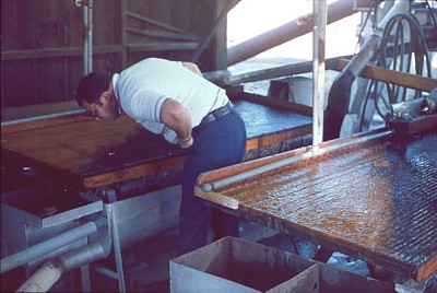 | |
 | ||
| In practice, mineral particles stratify in the protected pockets behind the riffles. The finest and heaviest particles are forced to the bottom and the coarsest and lightest particles remain at the top. These particle layers are moved across the riffles by the crowding action of new feed and the flowing film of wash water. The riffles are tapered and shorten towards the concentrate end. Due to the taper of the riffles, particles of progressively finer size and higher density are continuously brought into contact with the flowing film of water that tops the riffles, as lighter material is washed away. Final concentration takes place in the unriffled area at the end of the deck, where the layer of material at this stage is usually only a few particles deep. The separation process is affected by a number of factors. Particle size is especially important, but particle shape is important as well. Generally, as the range of sizes in feed increases, the efficiency of separation decreases. A well classified feed is essential to efficient recovery. Separation is also affected by the length and frequency of the stroke of the deck drive, usually set to 1 inch or more with an adjustable frequency that varies between about 240 to 325 strokes per minute. A fine feed requires a higher speed and shorter stroke than a coarse feed. The shaking table slopes in two directions, across the riffles from the feed to the tailings discharge end and along the line of motion parallel to the riffles from the feed end to the concentrate end. The latter greatly improves separation due to the ability of heavy particles to “climb” a moderate slope in response to the shaking motion of the deck. The elevation difference parallel to the riffles should never be less than the taper of the riffles; otherwise wash water tends to flow along the riffles rather than across them. I have a page on How to Build Your Own Shaker Table | ||
| Spiral Concentrators Spiral concentrators are modern, high capacity, low cost units developed for the concentration of low grade ores. Spirals consist of a single or double helical sluice wrapped around a central support with a wash water channel and a series of concentrate take-off ports placed at regular intervals along the spiral. To increase the amount of material that can be processed by one unit, two or more spirals are constructed around one central support. The newer Humphreys spirals are capable of recovering particles as small as 270 mesh (53 microns). In a test at CSMRI, a new Mark VII Reichert spiral recovered 91.3% of the free gold contained in the feed in a concentrate representing only 5.4% of the feed weight. The unit showed little decrease in gold recovery efficiency with material down to 325 mesh (45microns). |  | |
| Sand and Gravel Mines Finally, there is the issue of placer gold recovery from sand and gravel plants. Gold recovery in the typical sand and gravel plant presents problems not normally associated with placer gold mines. Recovery systems must be designed to interface with an existing sand and gravel operation. This usually limits the type and amount of equipment that can be used and, consequently, reduces recovery. In addition, extreme variations in feed rate occur because the sand and gravel plants operate in response to demands for sand and gravel, not gold. Variable feed rates may reduce gold recovery by causing recovery equipment to function erratically. Normally, in most sand and gravel operations, the material being mined has not been evaluated for gold content. In these cases, gold recovery cannot be accurately calculated, and the only measure of success is the extent that the value of the recovered gold exceeds the cost of processing. | ||
Comments: 0
Post a Comment